Easy to Build Autonomous Robot Car (with Code)
For my 5th semester project at the University, I decided to build an autonomous robot car. I encountered many obstacles along the way, and as a result, also learned a lot. In fact, my Raspberry Pi, which was initially the car’s brain, encountered a hardware failure. So, I had to take another route.
In this article, I’ll cover the two approaches I worked on. Hopefully, this article and the referenced source code shall help the reader with their own project of a similar nature. The two approaches were as follows:
- Approach 1: Raspberry Pi (as the primary processing unit + camera) + an Arduino (as the hardware instance)
- Approach 2: PC (as the primary processing unit) + Mobile Phone (as the camera) + an Arduino (as the hardware instance)
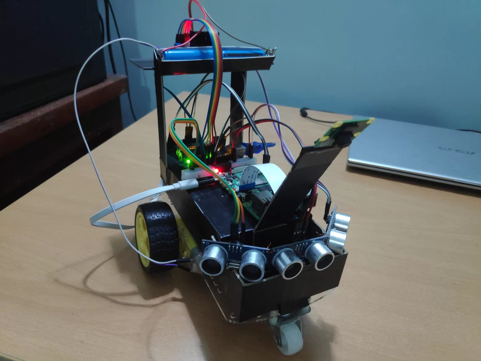 Approach 1 Robot
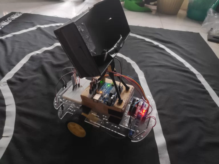 Approach 2 Robot
Overview
I’ve provided the component names and their respective prices for the first approach on the GitHub repo, but I wouldn’t rely too much on the prices because they should be way higher now due to inflation. I’ve also documented my journey during the project, so feel free to check it out if that seems interesting.
The following is a somewhat high-level architectural diagram for the system:
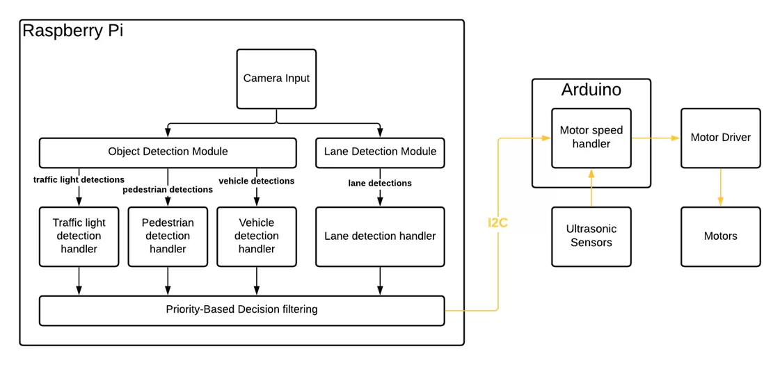 Approach 1: Architecture
Let’s talk a bit about each of these components and what they do. Afterward, I’ll give an overview of which parts of the source code correspond to which components. If you already have all the components and if the architecture diagram gave you a decent idea of how I’m using the components, feel free to skip the next section.
Components
The Robot Body (Chassis)
The entire robot was built on top of the components from a car chassis kit. This came with 2 DC motors and their wheels, two speed-encoder wheels, a battery box, and the front balancing wheel. I used rechargeable batteries with the battery box and used an additional power bank to power all the remaining components, including the Raspberry Pi and the Arduino.
To control the motors, I used an L298N Motor Driver. You can find more details about how to make the connections, here.
The Robot Brain + Camera
To begin, the camera takes an input image and passes it to both the Object Detection Module and the Lane Detection Module. For object detection, I’ve chosen 3 categories: Traffic lights, Pedestrians, and Vehicles. You can find more details on how to build the object detection model using Tensorflow Object Detection API, here.
On the other hand, the lane detection module handled the task of detecting and controlling the robot such that it stays within the lane.
Another thing to note is that the object detection module decides the speed of the robot, whereas the lane detection module decides the direction of the robot.
The Hardware
I initially used a Raspberry Pi 4 Model B as the brain of the system. This was paired with Pi Camera Module V2 for capturing images that would be fed into the Raspberry PI.
After the hardware failure with the Raspberry Pi, I decided to switch to the PC for all the processing. Of course, this meant that I can no longer use the Pi Camera to get the camera inputs. This also meant that I cannot have direct communication with the Arduino board.
To kill two birds with one stone, I decided to add a platform for my mobile phone. Accordingly, the system works as follows:
The phone camera sends its video stream to the PC via a WebCam app. I used the Iriun app to handle this. Then, the PC reads this video stream and does all the required processing to calculate the wheel speeds. The calculated wheel speeds are sent directly to the Arduino via Bluetooth. I used an HC-05 Bluetooth Module for handling this communication. Refer to the Source Code section to find the code for this.
The Hardware Interface (Arduino)
The Arduino I used was an Arduino Uno. It had almost exactly the number of pins for all the components I had, so it was perfect for this case. That being said, if you may wish to increase the number of Ultrasonic sensors. In that case, you would need a different board (or a multiplexer), so keep that in mind when picking the board.
Once the above modules calculate the wheel speeds from within the raspberry pi, it sends the speeds to the Arduino via an I2C connection. I won’t go into details on how the connection was set up, but here’s an excellent video on it.
The Arduino is connected to the following:
- The Raspberry Pi
- Three HC-SR04 Ultrasonic Sensors
- One L298N Motor Driver, which in turn is connected to the two DC motors that came with the chassis
If the distances detected from the ultrasonic sensors fall below a certain threshold, the speed suggested by the Raspberry Pi is overridden, and the robot stops. This acts as a failsafe in case the object in front is not one of the model’s detection classes.
The Arduino converts the finalized speeds into the scale of the speeds accepted by the motor driver and sends the signal which then passes to the motors.
Source Code for the Robot
As mentioned previously, you can find the source code for this project in the GitHub Repo. In addition, I will provide the structure for the important parts of the code base, so you can easily find what you’re looking for. I will only reference the code related to the 2nd approach (with the PC) because I discontinued the code for the Raspberry Pi after the failure. Therefore, it doesn’t include the code for object detection. However, the object detection module from the PC should be usable on the Raspberry Pi with very few changes.
Arduino/ - Contains all the used Arduino sketches
├─ fail_safe_unit_test/ - Sketch to test each ultrasonic sensor
├─ hc05_bt_test/ - Sketch to test the Bluetooth connection
├─ motor_control_with_failsafe_and_bluetooth/ - The main sketch that's finally running on the Arduino
PC/
├─ LaneDetectionModule/ - Contains all the code related to lane detection (lane_detection.py)
├─ MovementModule/ - Contains all the code related to movement (movement.py)
├─ ObjectDetectionModule/ - Contains all the code related to object detection inference
│  ├─ tf_utils/ - A set of tensorflow utility scripts used by the object detection inference
│  ├─ detect_test.py - Python script to test the inference on a video stream
│  ├─ label_map.pbtxt - A file containing the labels that are detected by the module
│  ├─ object_detection.py - The main python script used for object detection
│  ├─ od_handlers.py - Python script to get the speeds based on the detections
├─ main_PC.py - The main python script that runs on the PC
├─ threaded_main_PC.py - A threaded version of main_PC.py. Recommended for running.
├─ motor_bluetooth_test.py - Python script to manually send wheel speeds via Bluetooth for testing
Final Remarks
Hope this was helpful. You should find a lot more details in the GitHub repo for the project, including my attempts at adding speed encoders along with a feedback loop (PID). Feel free to reach out if you run into any errors or other issues.
Also, take a look at another project of mine that combines AI with embedded systems: Building a device for navigating in 3D.
To see some of my other Computer Vision-related articles, head over to the Computer Vision category.